Vertical Form, Fill, and Seal (VFFS) machines are used in the consumer products industry for a wide variety of packaging applications. Various products like salt, tea, sugar, spices, snack foods, wafers, detergent, candies, milk, sauce, etc. are placed into formed pouches and then sealed. The pouch material is flexible and typically heat-sealable plastic. Paper is also used and sealed by glue.
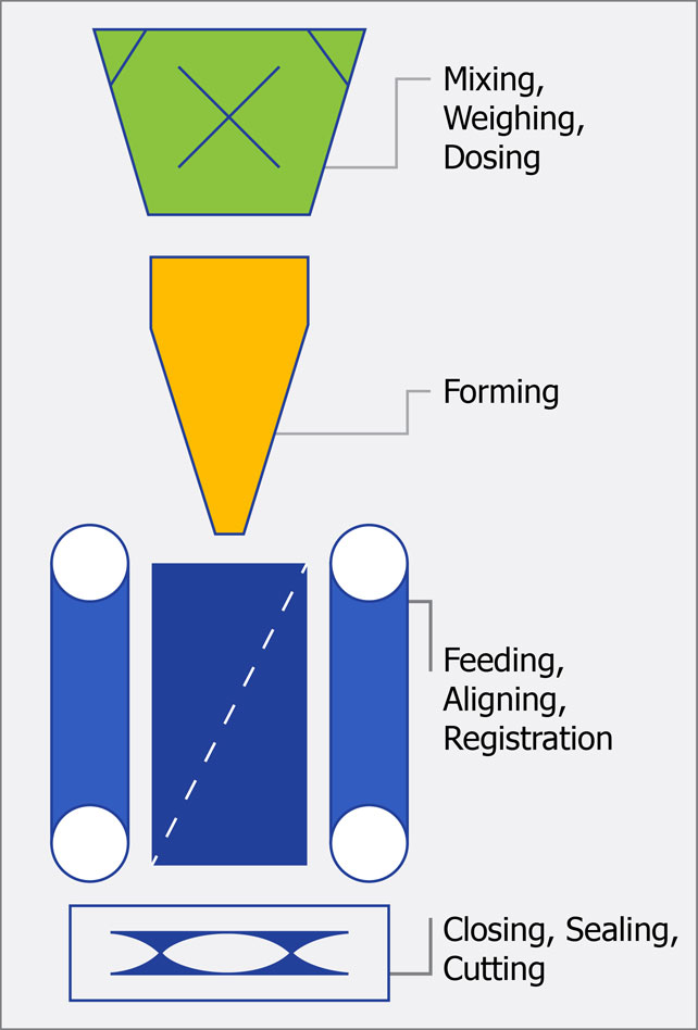
The VFFS machine can be divided into four functional areas:
- Mixing, Weighing, Dosing
- Forming
- Feeding, Aligning, Registration
- Closing, Sealing, Cutting.
Typically,
Fully automatic VFFS machines require limited operator intervention. The operator need only replenish product by loading supply hoppers or changing packaging film drums. For machines that are semi-automatic, operators are required to perform part of the packaging operation.
VFFS machines can be intermittent or continuous motion. Intermittent motion machines operate on the principle that vertical bag seals are made when the film is moving and horizontal seals occur when the film stops. Intermittent motion machines offer a suitable solution for applications where speed is not absolutely paramount.
Continuous motion machines operate on the principle that both vertical and horizontal bag seals are made when the film is in motion. These machines operate at the highest attainable speeds and require a reciprocating sealing jaw motion format.
There are two major process advantages for a continuous motion machine over an intermittent type:
- Faster cycles times. On a continuous motion machine the cross jaw moves with the film and can perform the horizontal sealing application while the film is still moving. The typical intermittent machine operates at 60 to 80 packs per minute (ppm) maximum, while a continuous machine can operate up to speeds of 180 ppm. The highest machine speed attainable is determined by the weighing mechanism.
- Control over the cross jaw along the vertical plane provides additional bag making possibilities.
Generic VFFS Machine Process
A roll of film is unwound and formed into a tube over a forming collar. A vertical overlap seal is applied to the tube by the vertical sealing bars. A bottom seal is created by the horizontal sealing bars in the cross jaws.
The formed pouch is then filled with correct amount of product while the film tube is being fed by the film transport belts. Often a precision scale or an auger ensures that the proper amount of product is placed in the pouch in a consistent manner.
After the correct length of film tube has been fed, a top seal of the filled pouch is created by the horizontal sealing bars, while the filled pouch is cut from the descending film tube by a knife in the cross jaws.
If the film is pre-printed, a registration sensor is added to the system to correct the film position in order to maintain the correct print position relative to the end of the pouch. The bottom seal creation of the empty pouch, top seal creation of the filled pouch and cutting of the filled pouch all occur at the same time.
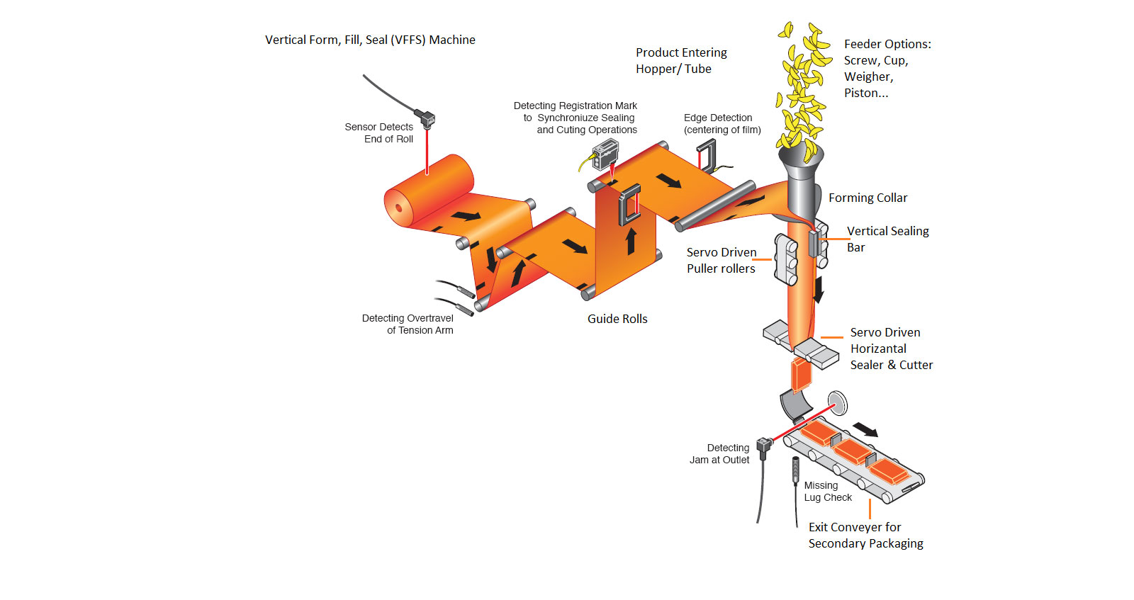
1. Film Unwind
Film unwind is responsible for unwinding film into the machine, providing operator ease-of-splice (optional), roll change-out features (optional) and film tension. Many unwind sections are static mandrel (un-powered) types and use either a pneumatic brake or friction brake to control unwind action and provide applicable film tension. Although, occasionally the unwind mandrel will require VFD, Servo or DC gear motor type control.
In the unwind section often there are roll change features, such as dual mandrels, roll lifts and vacuum splice bars. A vacuum splice bar is a horizontal bar with a vacuum manifold built in and a small horizontal slot (suitable to accommodate a utility knife blade) through the middle of the bar. The unwind section will also include the film tension and / or dancer. The dancer can provide a speed feedback (analog or discrete) to the unwind control circuit, as well as a film accumulator area for bag index purposes, especially on an intermittent type machine. Additional options possible for the unwind section are functions like zipper applicators and breather inserters.
2. Film Registration
This section includes the film registration sensor and placement adjustment mechanisms. The film registration is used on film with graphics or pre-printed information. Printing process variations, film stretch, film slippage during acceleration and other factors can allow the graphics to drift away from ideal cosmetic / marketing placement on the finished bag. The registration mark provides a method to make minor adjustments to the actual end placement of the seal and cut on a bag. When there is no printing or graphics on the bag, the process is defined solely on length. Also located in the film registration section, it is common to have the film alignment / tracking adjustment mechanisms. These are used to ensure the film stays in the correct place on the forming tube.
3. Forming Tube
The forming tube mechanics are often unique designs for different machines, films and products. However, the general description is an inverted cone with radius corners. This cone and the correct diameter tube (shapes can differ from round for special package needs) are combined to form the flat film into a tubular or tunnel type shape, which ends up being wrapped around the external surface of the actual forming tube. In order to provide extra film for the long or “back” seal, the width of the film will be greater than the circumference of the forming tube. The long seal is formed by several different heater mechanical configurations that are typically placed on the front of the forming tube and are eight to twelve inches in length. Linear film speed and type are factors in determining the correct minimum length of the long seal. There are two main types of long seal.
The first type of long seal is the static bar, which is a heated bar with heating element and thermocouple. This bar will be engaged into the film and forming tube only while the film is in motion with slight timing delays to prohibit melting of the film when stationary. There can also be two bars, but placed where they are facing one another in a manner to allow the long seal flaps to be placed in between the two bars. This method is used instead of the overlapping method used for single bar configurations. This can provide stronger seals / seams and the product ambient temperature (i.e. forming tube temperature) will have less of a factor on the loop control.
The second type of long seal is the dynamic belt, a single-heated stainless steel belt with two pulleys. A heated plate transfers the heat to the stainless steel band or belt and is engaged into the film and forming tube while the film is in motion. Like the static bar type, there can also be dual dynamic belts / bands. The benefit of dynamic belts is they can move with the film and also be adjusted to operate faster than the base film speed or even slower. These are process decisions made based on many product, machine and material factors.
4. Film Pull Belt(s)
There are typically two film pull belts – right side and left side. They are typically vacuum belts, which allows for better gripping control in dusty, high moisture or cold operating environments. The belt mechanics are often powered by VFD motors with encoder feedback, servo axes or perhaps stepper motors. Occasionally there will be only one motor that is mechanically transferred to the separate belts, but the general practice is to eliminate the additional special mechanical costs in lieu of the additional, but more flexible, controls cost. The film pull belts provide the actual force to pull the film through the machine and are used to maintain good film tension on the forming plow and tube. Often code is used to monitor position and velocity error to ensure that slight mechanical differences are not allowing one side to pull more than the other.
5. Cross (Sealing) Jaw
The cross jaw is responsible for three major functions—to seal the top of the previously filled bag, to create the bottom seal for the soon to be filled bag and to cut or separate the completed bag from the bottom of the new bag.
The front and back cross jaws operate as a pair. The front and back jaw will both have a top seal area (horizontally) and a bottom seal area. Additionally, either the front (typically due to maintenance reasons) or the back jaw set will have a knife which runs horizontally in the middle of the jaw face. This knife is recessed and is activated by a pneumatic actuator. The opposite jaw set will contain the anvil for the knife.
Each jaw will have one or two heating elements as well as a thermocouple for temperature control. Additionally, the cross jaw section can have options like product wipers, bag deflators, bag hanger punch, gusset (single & double) creation mechanics and flat bottom bag mechanics to name a few. Cross jaws are typically configured mechanically where the front and back jaws interpose each other and therefore meet in the vertical centerline of the bag and forming tunnel. However, there are also versions where either the front or back jaw is stationary and the opposite jaw is moveable. Servo drive/motor combinations, VFD drives with induction motors and high power pneumatic cylinder actuators are used to close the jaws and provide the necessary sealing pressure to provide a suitable bag seal. It is very common for the jaws to contain built-in springs to allow for some closure error as well as a default force. Often, position and torque data are monitored for the cross jaws. This data can easily be used to detect product in the seal or between the jaws. Anytime there is product in the seal, these two bags should be discarded due to potential seal / seam leakage.
The previous sections are typical for an intermittent VFFS machine; however a continuous machine will often contain a section called the rotary or vertical jaw, depending on the bagger type.
6. Rotary Jaw
The first type of continuous bagger is the rotary / “D” jaw. For a rotary type bagger, the horizontal plane motion for the front and back cross jaws is replaced with a rotary type motion. This is accomplished with special mechanisms, orbital gearboxes and/or four-bar type linkages. In general each jaw is attached between two gears. Each jaw end gear is actuated by a driving gear. Along with some orientation linkages, these jaws will operate in a “mirrored” fashion so the jaws maintain the same distance to the vertical plane as they rotate in a top-to-bottom and around fashion. The main benefit of a continuous type bagger over the intermittent is that since the cross jaw is now moving along the vertical plane as well as the horizontal plane, the sealing process can occur without stopping the film completely.
7. Vertical-Jaw
The second type of continuous bagger is the box or square jaw type. This differs from the rotary jaw in that there are now two mechanical movers for the overall cross jaw – one is the horizontal-only plane and the other is for the vertical-only plane. Although this adds increased controls and mechanical costs, it can also provide additional bag making process options, longer bags with fewer constraints and more control for product sweeping type functions. Mechanically, the cross jaw mechanics and motor are contained on a carriage. This carriage is controlled and moved along the vertical plane via the vertical mechanics and motor.
Machine Speed
The speed of the VFFS machine is the rate at which it is able to (1) form the pouch (bag, sachet, etc.); (2) fill it with product; (3) seal it; (4) cut it; and (5) transfer the package for shipment or further end-of-line packaging such as a case packer, over wrapper etc. The speed of the machine is one of the main attributes in many end users’ buying criteria. Machine builders will design their machines to operate at the highest speed possible.
Challenges
- How to design the mechanics of the machine to operate at high speed and maintain the correct tension of the film feed in order to maintain the quality of the packaging.
- How to position the film accurately based on eye mark registration.
- How to design the optimum sequence of machine operation.
Refer to the timing diagram below for an example of a Form, Fill and Seal operation in intermittent duty cycle. This is an example of typical VFFS machine with an auger screw filling system.
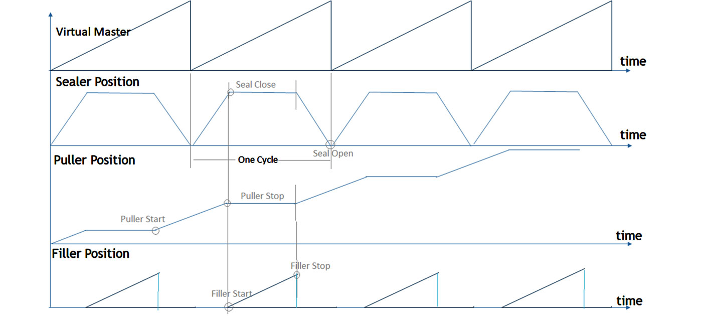
Filler Types:
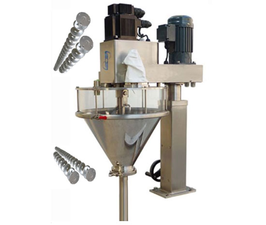
- Auger: Auger is screw feeder generally driven by Servo Motor. Motor Rotation defines material loaded in the Pouch. This is suitable for Powder, Grains, Chips.
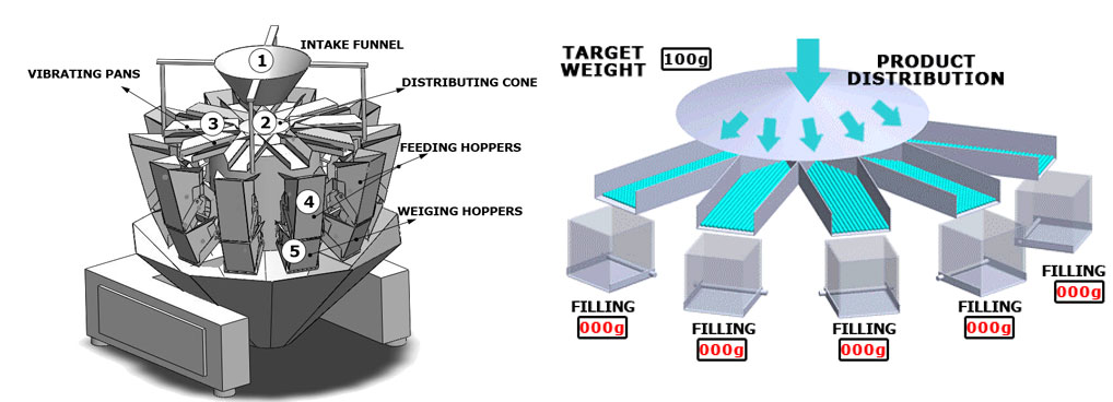
- CUP Feeder: This is Multi-head feeder. Suitable for high speed Machines, where the material is ready to be dropped. This is also equipped with weighing mechanism. It has separate control mechanism which handshakes with Machine Controller. This mechanism also supports both volumetric & weigh feeding.
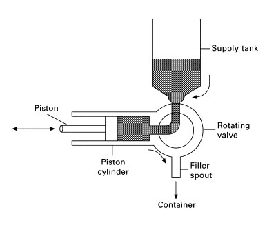
- Piston type Feeding: This is suitable for generally Liquid and viscous material like sauce, jam. Piston is driven by Servo Motor. Suction stroke is used for loading the material and Discharge for dispensing it in the Sachet. It has suction and discharge valves.
End Users expect VFFS to be:
- Productive: Optimize packaging process to achieve maximum possible machine speed; maximize throughput with highest quality; high accuracy and shorten recovery time.
- High performance: Satisfy strict accuracy requirements at high machine speeds and variable bag lengths.
- Flexible: Release the burden of manual adjustment of film registration sensor position by introducing software adjustment scheme; improve changeover time.
- Easy to use: In spite of machine complexity, machines must be easy to maintain and operate.
Machine Builders expect VFFS to be:
- Modular and scalable: Mix and match VFFS machine functions that are ideally suited for specific customer applications; customized functions to develop a new machine that is localized to market demands.
- Standard: Develop and document mechanisms common to VFFS machines that can be easily redeployed with minimum modifications, despite different machine sections/conditions that result in more complicated sequencing and interlocking, so that machine design and development time can be reduced.
- Cost-effective: Machine integration, mechanical, electrical optimization and wiring start up time costs are reduced.
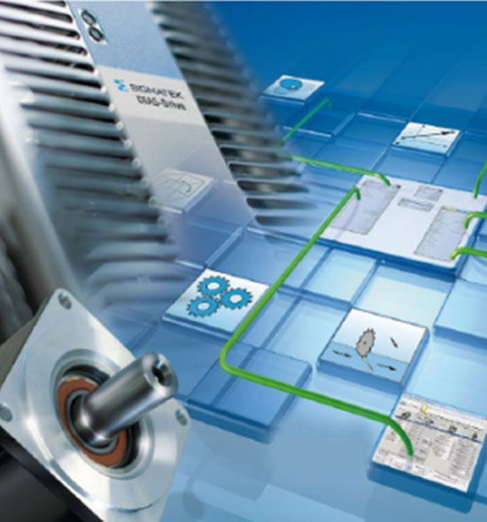
Our Sigmatek Solution:
- S-Dias CPU CP112 with Varan Port, Ethernet Ports, with modular construction
is best fit above application. - Varan Port supports Motion and I/Os.
- Lasal Class Engineering Platform.
- Safety CPU Enhancement.
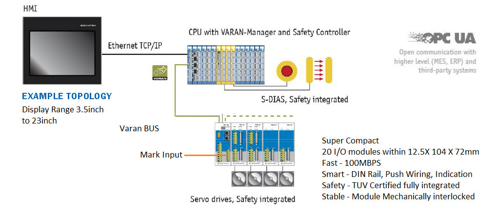
VARAN Bus:
- HARD REAL-TIME Bus cycle times under 100 µs / Jitter less than 100 ns
- FLEXIBLE NETWORK TOPOLOGIES Modular machine design with star, line, tree topologies
- SIMPLE AND ECONOMIC Protocol completely implemented in the hardware, use of inexpensive FPGAs for managers and clients
- OPEN STANDARD The manufacture-independent VARAN Bus User Organization holds the rights to the open technology
- AND MUCH MORE Automatic addressing, Direct Access, multi-manager capable, CanOpenimage
ENGINEERING TOOL - LASAL
- Object-oriented programming and project design
- Visualisation
- Drive technology
- Safety configuration
- Tools for service, remote maintenance,
updates and data exchange

HOT FACTS
ALL-IN-ONE – ONE toolset for all development phases; short time-to-market
OBJECT-ORIENTED – High modularity and reusability
GRAPHIC REPRESENTATION – High clarity
READY-TO-USE FUNCTION COMPONENTS – Reduce software development up to 70%
MOTION CONTROL
High-performance, flexible & economic complete solution
for highly dynamic and exact servo applications: drives, motors,
gears, software
All configuration data and parameters centrally in the control-
initial start-up, service and exchange simplified
Perfect communication connection to the CPU via real-time
Ethernet VARAN bus
HOT FACTS
COMPACT DRIVES – save space in the control cabinet
COMFORTABLE – library with predefined motion templates
FLEXIBLY – control different motors, standard feedback systems
ABOUT MESSUNG SERVO & MOTION CONTROL AUTOMATION
Messung is Master Distributor – India for Sigmatek, Austria. Together, Messung-Sigmatek deliver fully integrated, future-oriented servo & motion control solutions in India, incorporating programmable logic controllers, motion control systems, drive products, HMIs and SCADA, and much more – to bring flexibility, consistency and long-term availability for packaging machines.
Messung is the pioneer of the PLC, one of the leading PLC automation companies in India, providing cutting-edge industrial automation & control solutions. With four decades of experience in the industry and a history of continuous innovation, global partnerships and pro-active R&D, Messung is the ideal partner for machine automation & control solutions in India.
Messung partners with packaging machine builders to create tailored solutions that enhance the performance and value of their machines. Messung’s automation and controls solutions can help automate single machines or complete factory lines, ensuring operational accuracy, repeatability and stability.